Qualisys Air Calibration
First of all decide your overall region of interest (RoI) where robots with markers on them need to be tracked by the Qualisys system. An example of RoI is the water tank’s surface area. It is acceptable that one camera cannot cover the entire RoI, however together, all cameras need to be able to cover the entire RoI.
Select one camera to be calibrated. Start by placing 2 markers as far away in the RoI but still within sight of the camera (i.e. on the boundary of RoI). See Fig. 132 for an example. The distance between the two markers needs to be representative of the pattern that you want to place on your robot. For small robots, the markers will be closer to each other, whereas for larger robots the markers can be further apart. However, when the pattern turns, we want the camera to be able to distinguish between the two markers. When it comes to calibration, there are 2 parts: hardware and software.
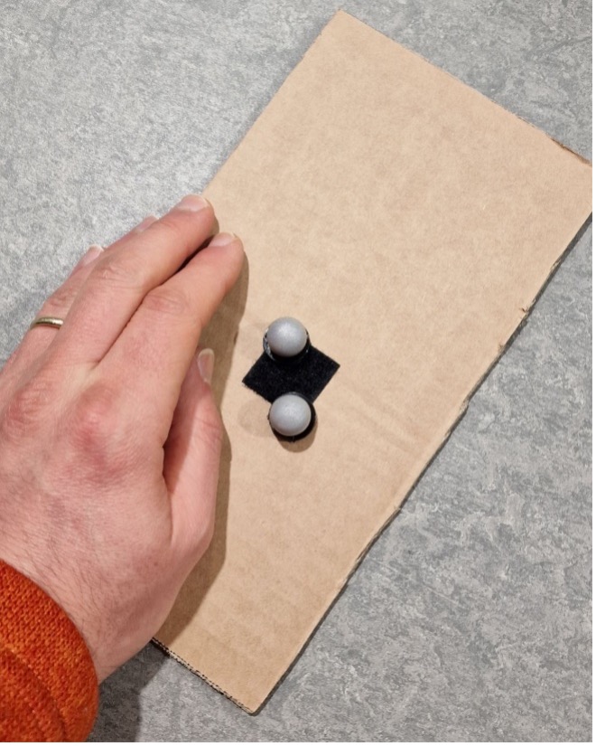
Fig. 132 Example of Qualisys marker placement for calibration
Hardware Calibration
The hardware calibration use the rings that are attached to the camera. There are 2 rings on the cameras corresponding to Aperture and Focus that need to be set up. See Fig. 133 for an example.
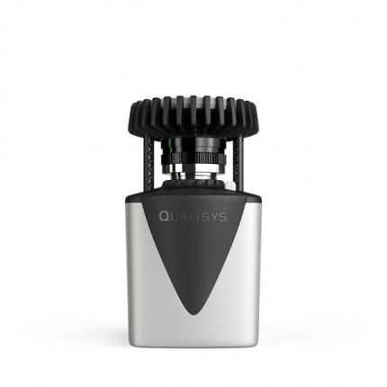
Fig. 133 Qualisys Air Camera Rings
The aperture defines the quantity of light that gets inside the camera. During the Qualisys training 14-15 June 2023, the instructor set all cameras to 2.8. Smaller number means more light but less depth (think of markers being seen as too bright). Larger number means less lightless light but more depth.
The focus makes parts of the image clear to the detriment of other parts that might appear blurry. Say we focus on a point located close to the camera (select a low value for focus). Then, the surroundings located far away will appear blurry. The other way around, say we focus on the surroundings located far away (select a large value for focus, say infinity). Then, the nearby point will appear blurry.
A Guideline for the aperture and focus values
First, Select video mode for that camera. See Fig. 134 for an example.
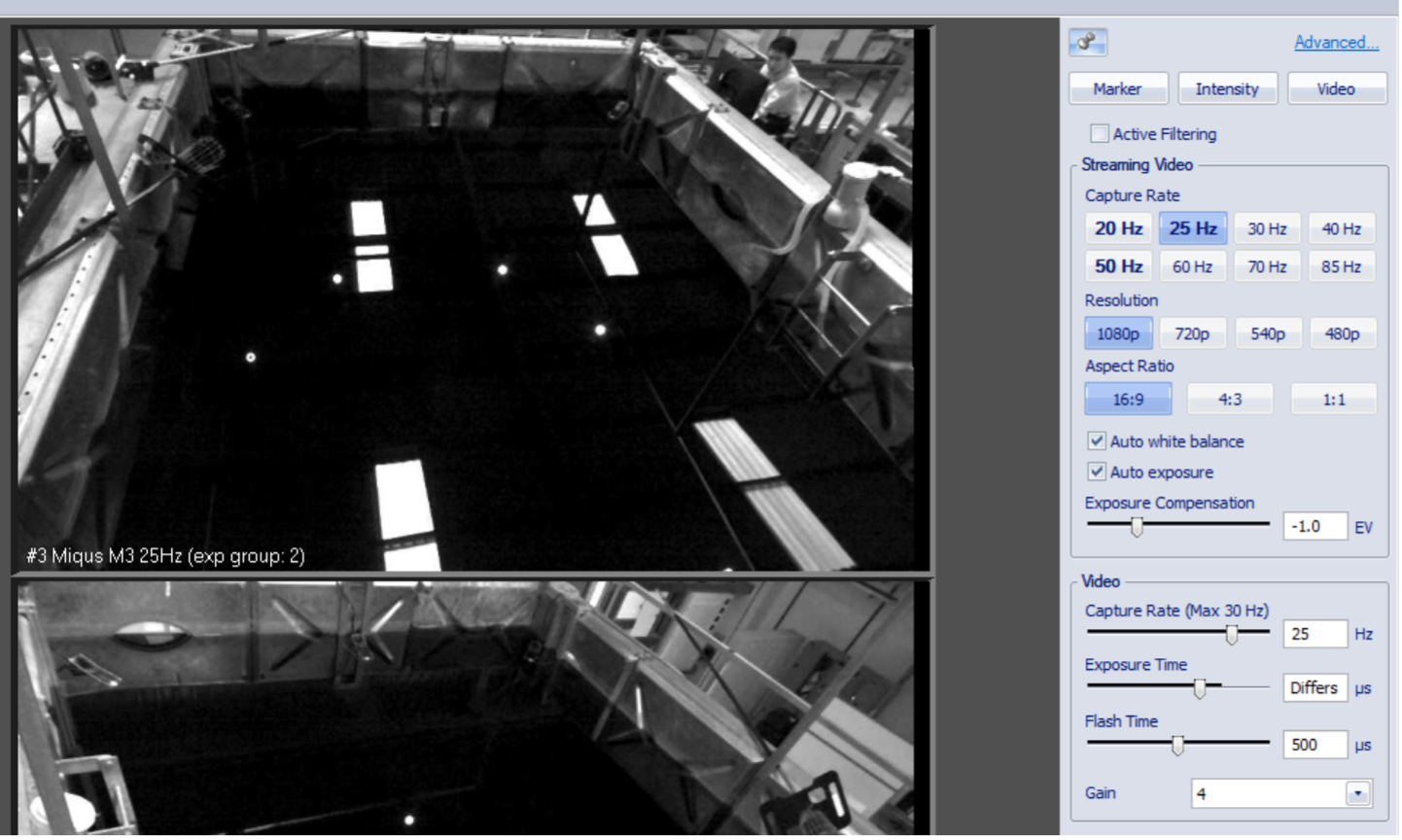
Fig. 134 Qualisys Air Camera Video Mode
Start by setting the focus ring to infinity. The reason is that we want to be able to see the whole scene as clear as possible, instead of focusing on a particular point in space that might be located closer to the camera. In the video, zoom on the two markers that had been placed on the boundary of RoI. What we are looking for are two bright objects, see Fig. 135.
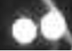
Fig. 135 Qualisys Air Camera Focus
The aperture is related to the frequency of data collection. The higher the frequency rate, the more light needs to get inside the camera for an object to get the chance to be recognised.
Software Calibration
There are two software parameters that need to be set up: the Exposure & Flash Time (ET) and Marker Threshold (MT).
ET sets up how long the light ring should be on during a sampling time T (say the Capture Rate is set to 100 Hz, then T=0.01 sec).
The higher this value, the more light the cameras emit.
MT Setting Up
Firstly select the Intensity mode. See Fig. 136 for an example.
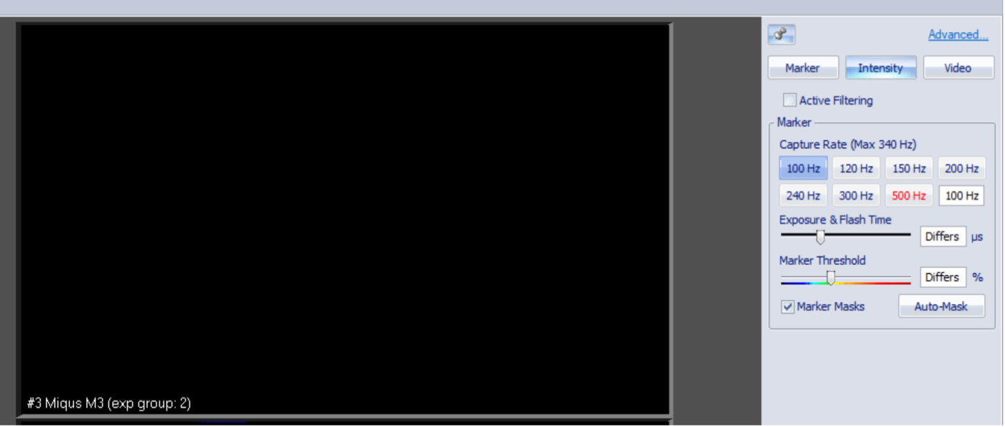
Fig. 136 Qualisys Air Camera Intensity
The light ring on the camera turns on in green. See Fig. 137 for an example.
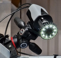
Fig. 137 Qualisys Air Camera Green
As a guideline, we are looking at ET to be from 50 to 300 microsecond, and MT to be between 20 to 60 %. Start with low ET and MT values and check whether the two markers are clearly identified. If not, try increasing ET initially and MT afterwards, then reiterate, meaning increase ET and then MT. Satisfactory results would look like in the images below. Two clear and separate balls had been identified. See Fig. 138 for an example.

Fig. 138 Detected Markers
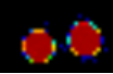
Fig. 139 Detected Markers
Next, set to Marker mode. See Fig. 140 for an example.
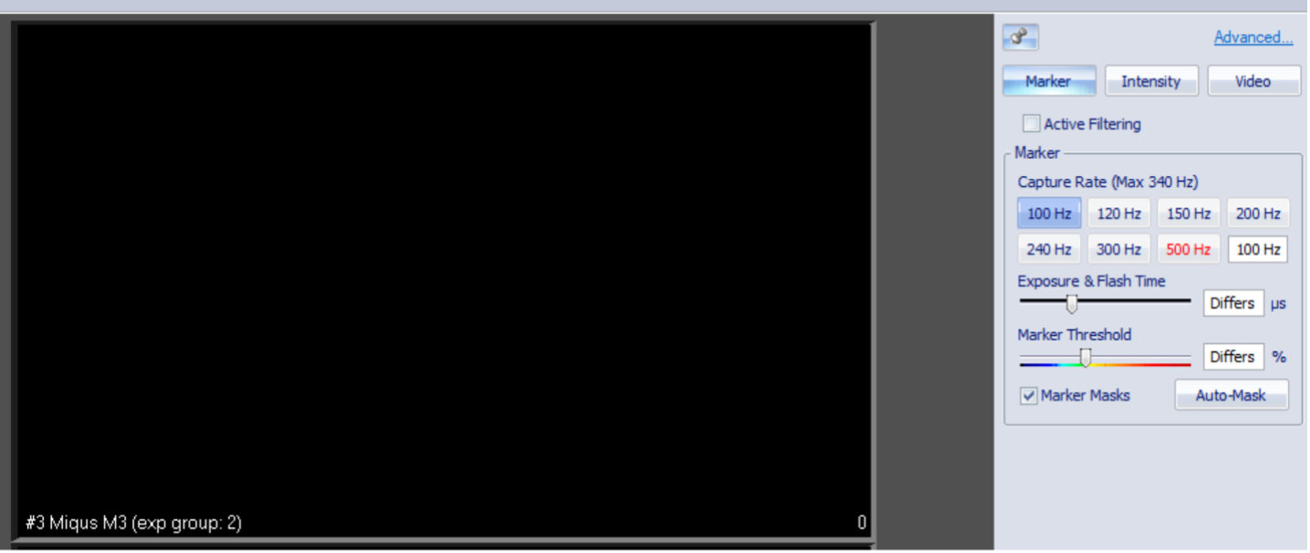
Fig. 140 Qualisys Air Camera Marker Mode
and zoom on the two markers. We want to be able to see them clearly and distinct like below. See Fig. 141 for an example.

Fig. 141 Detected Black Markers
Next, we need to look at artefacts. Although markers might be clearly identified using the settings above, this might come at the expense of artefacts, as seen in the Fig. 142.
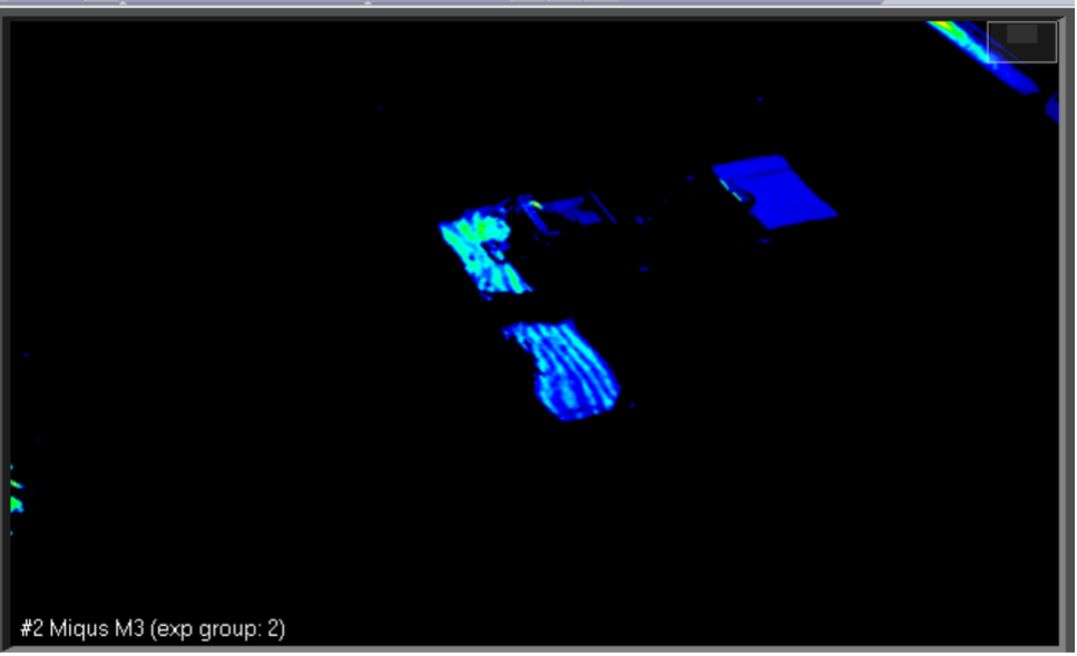
Fig. 142 Qualisys Artefacts
Now, we need to revise ET and MT parameters such that there is a balance (trade-off) between the clarity of the identified markers and the reduction of artefacts (ideally, we want to see clear markers and make artefacts disappear).
Note
Artefacts: not useful objects that get picked up by cameras, such as reflections, shadows, etc.
Try switching to Video mode and see what creates those artefacts. If the source of the artefacts are physical objects
like aluminium rods lying in the RoI, then physically remove/eliminate them by placing them somewhere else,
away from the scene. Other examples of artefacts include water reflections from the outside light coming through
the roof windows, which cannot be physically removed. Instead, we can try to reduce its effects by tuning/playing
with the ET and MT parameters. And redo Step 3 for all tracker cameras.
Masking the Artefacts
After having put all effort in eliminating or at least reducing the effects of artefacts, the leftovers need to be masked. First, make sure to remove any markers from RoI so that what is left over are just artefacts. Two options: Auto-Mask or Manual Masking.
1. Auto-Mask: Select the Auto-Mask mode with clicking the Auto-Mask button at the right hand side of the menu.
See Fig. 143.
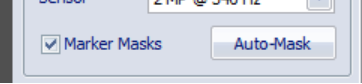
Fig. 143 Qualisys Auto Mask
2. Manual Masking: Click on the Marker Mask Tool at left-hand side menu.
Then use the mouse to draw rectangles on each camera representing the region to be masked.
See Fig. 144.
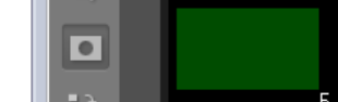
Fig. 144 Qualisys Manual Mask
Define global coordinate system
To do calibration we will use the Calibration kit 600. Art no 130456, Serial number 2412, consisting of an L-shape
and a wand, shown at Fig. 145.
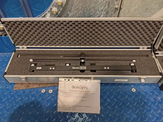
Fig. 145 Qualisys Calibration Kit
Place the L-shape somewhere in the Region of Interest (RoI) where you want the global coordinate system to be.
See Fig. 146.
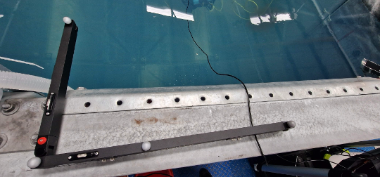
Fig. 146 Qualisys L-Shape
Next, take the T-shape 601.7 mm wand. Make sure to indicate the details of this kit
(consisting of the T-shape wand and L-frame) by going to Project Options -> Camera System -> Calibration.
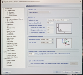
Fig. 147 Qualisys Project Options
Then, Click the wand icon on the top horizontal menu. See Fig. 148.
Fig. 148 Qualisys Wand Icon
and, on the window that pops up on the screen, choose the calibration time (e.g. 60 seconds) and
the Delay in calibration (e.g. 5 seconds), then hit OK. See Fig. 149.
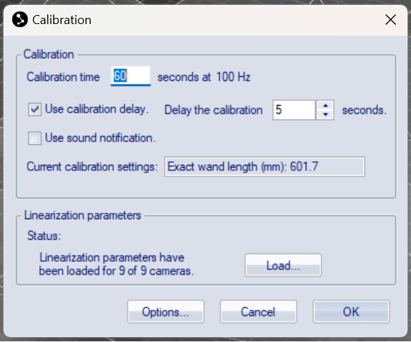
Fig. 149 Qualisys Calibration Time
Take the T-shape 601.7 mm wand and start waiving it in the RoI.
Combine the two motions below to create a waiving motion.
Move the wand round the tank in a
spiral motionwith the head of theT- wand vertical.Move the wand up-down with the head of the
T- wand horizontal.
Try to cover as much as possible of entire RoI (not just a small region). Once the data has been recorded, you can view and play it again.
Create a rigid body
For the tracking the rigid body, we need to create a non-symmetric pattern with the Air markers. See Fig. 150.
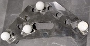
Fig. 150 Qualisys Rigid Body Example
Make sure the following three windows are available on the screen, hit View -> Trajectory Info -> Unidentified. Then hit Labeled and finally hit Discarded.
See Fig. 151.
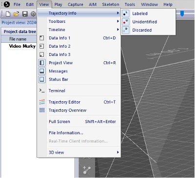
Fig. 151 Qualisys Windows
Click on the Record icon on the top horizontal menu. See Fig. 152.
Fig. 152 Qualisys Record Icon
and start capturing a short video that contains the pattern. See Fig. 153.
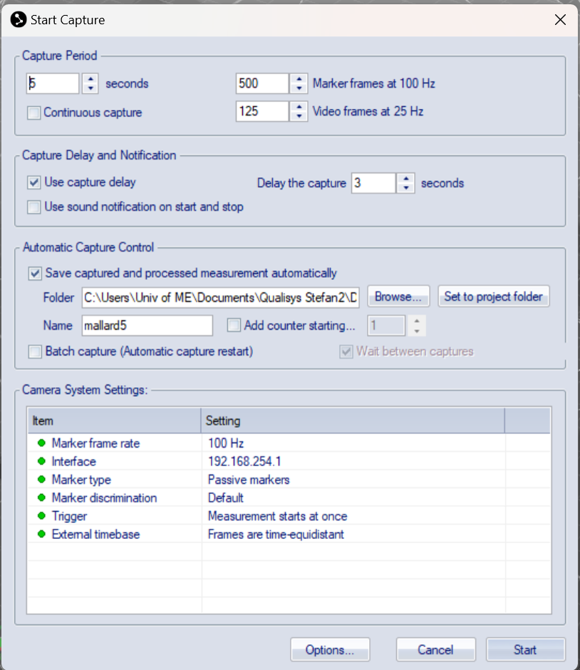
Fig. 153 Qualisys Capture Video
Replay the recording and pause somewhere (hit spacebar). Markers’ data will show up in the box Unidentified trajectories.
Click on each marker that forms the pattern, then drag and drop them into the Labeled trajectories.
Give individual markers and associated trajectories names, e.g. marker1, marker2, etc.
Select all markers that form a pattern. Use Shift + select, or Ctrl + click on each marker ball, right-click with the mouse -> Define rigid body (6DOF) -> Average of frames.
See Fig. 154.
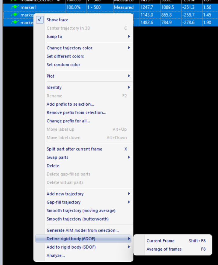
Fig. 154 Qualisys Rigid Body Creation
Then give it a name, as shown in Fig. 155.
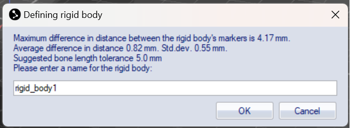
Fig. 155 Qualisys Rigid Body Name
Note
Make sure the name does NOT have any spaces, and does not start with a number, otherwise it would fail to work on ROS.
Note
In tutorial below, we shall work with a different rigid body called Mallard_pattern1 instead of rigid_body1.
Next, we need to adjust the body coordinate system, i.e. the xyz-coordinate axes.
For that, click on the settings button from the horizontal top menu. See Fig. 156.

Fig. 156 Qualisys Settings Button
and go to Processing > 6DOF Tracking. See Fig. 157.
Fig. 157 Qualisys 6DOF Tracking
Then, click on Translate button and adjust accordingly. See Fig. 158.
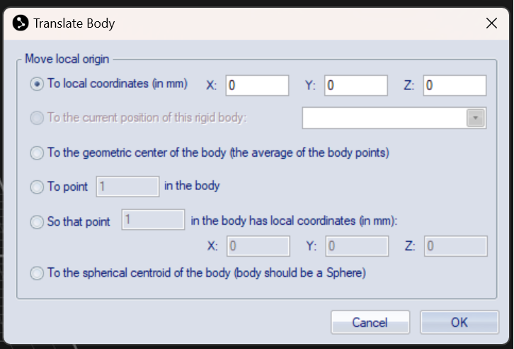
Fig. 158 Qualisys Translate Button
You can also click on Rotate. For example, below we set up the y-axis going through points 1 and 3. See Fig. 159.
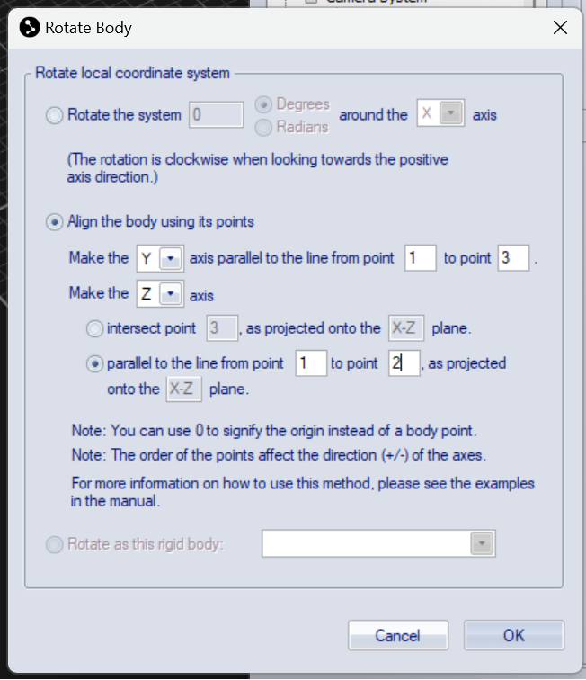
Fig. 159 Qualisys Rotate Button
To know which point has what number, click on a point and look at the number shown in the upper right corner of the white window. For example, below the point 2 was clicked on. See Fig. 160.
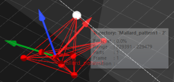
Fig. 160 Qualisys Point Number
To check the list of all rigid bodies stored in QTM, go to Project Options -> Processing -> 6DOF Tracking. See Fig. 161.
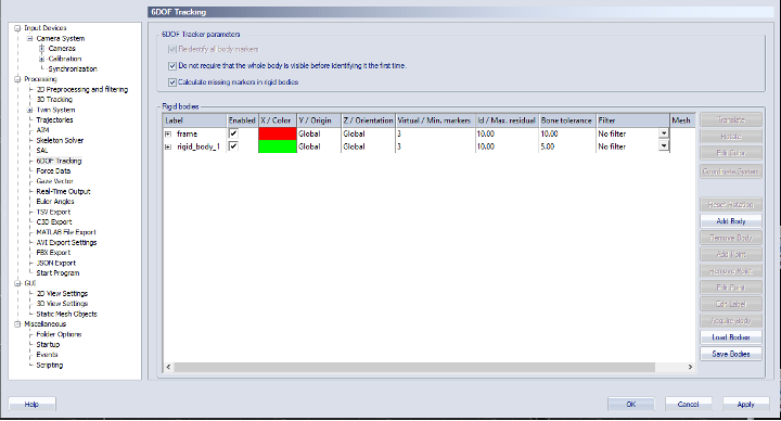
Fig. 161 Qualisys Rigid Bodies
Close the active window inside QTM (hit the second X from top to down, on the upper right corner of the screenshot above)
and when the dialog box appears, select Yes, save settings. Click the New icon to start streaming
(broadcasting) data of the rigid bodies defined above, across the network (the Netgear switch).
See Fig. 162.
Fig. 162 Qualisys New Icon
Continuously stream offline recorded data
Open a project which has recorded data in it. You should be able to see such files in the left-hand side menu of QTM. Select Play -> Play with real-time output.