Calibration
The calibration of the Qualisys system is a crucial step in the process of setting up the system. There are 2 types of calibration that need to be done: the hardware calibration and the software calibration.
Hardware Calibration
The hardware part has been done for you already, meaning the Aperture and Focus rings have been set up by a Qualisys trainer and then the camera was enclosed in its water sealing enclosure. Aluminium frames have been designed by the same Qualisys trainer based on what the overall region of interest (RoI) needed to be, where robots with markers on them needed to be tracked by the Qualisys system.
Software Calibration
There are two software parameters that need to be set up: the Exposure & Flash Time (ET) and Marker Threshold (MT).
ET sets up how long the light ring should be on during a sampling time T (say the Capture Rate is set to 100 Hz, then T=0.01 sec).
The higher this value, the more light the cameras emit.
MT Setting
First of all, place 2 markers that are close enough inside the water, as far away in the region of interest, but ensure they are visible by the camera you intend to calibrate. See the image Fig. 177 for an example.

Fig. 177 Underwater Markers
In QTM, select Intensity mode. See Fig. 178 for an example.
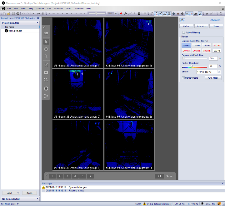
Fig. 178 Intensity Mode
As a guideline: start with ET=500µs and MT=40%. Start with low ET and MT values and check whether the two
markers are clearly identified. If not, try increasing ET initially and MT afterwards, then reiterate,
meaning increase ET and then MT. Satisfactory results would look like in the image Fig. 179.
Two clear and separate balls had been identified representing the 2 markers.

Fig. 179 Identified Markers
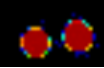
Fig. 180 Identified Markers
Next, set to Marker mode. See Fig. 181 for an example.
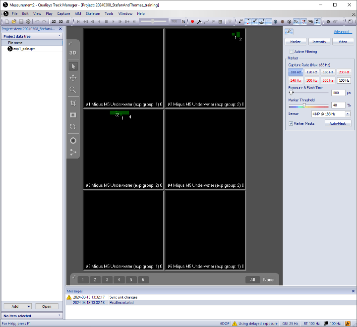
Fig. 181 Marker Mode
Zoom on the two markers. We want to be able to see them clearly and distinct like below. See Fig. 182 for an example.

Fig. 182 Identified Markers
Next, we need to look at artefacts.
The Artifacts means not useful objects that get picked up by cameras.
Although markers might be clearly identified using the settings above, this might come at
the expense of artefacts, as seen in the image below. Now, we need to revise ET and MT parameters
such that there is a balance (trade-off) between the clarity of the identified markers and the reduction
of artefacts (ideally, we want to see clear markers and make artefacts disappear). See Fig. 183 for an example.
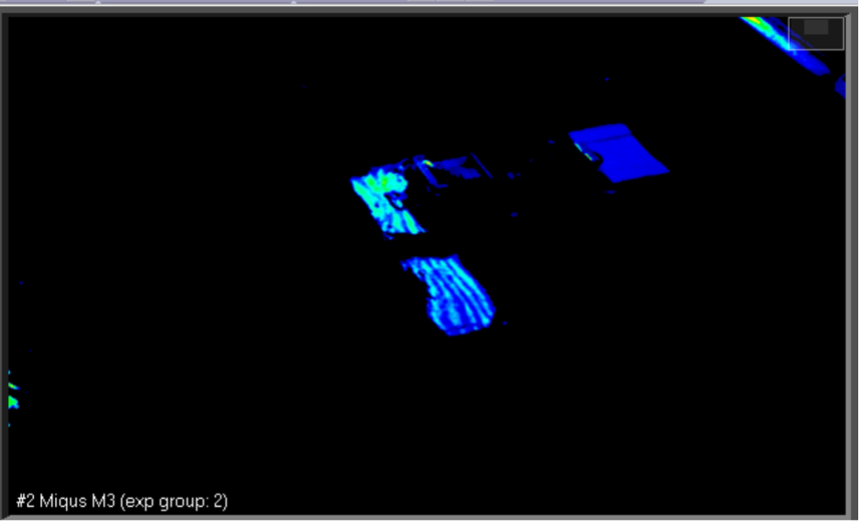
Fig. 183 Artefacts
Try switching to Video mode and see what creates those artefacts. If the source of the artefacts are physical objects like aluminium rods lying in the RoI, then physically remove/eliminate them by placing them somewhere else, away from the scene. Other examples of artefacts include water reflections from the outside light coming through the roof windows, which cannot be physically removed. Instead, we can try to reduce its effects by tuning/playing with the parameters ET and MT.
ANd then, redo Step 3 for all tracker cameras.
Masking artefacts
After having put all effort in eliminating or at least reducing the effects of artefacts, the leftovers need to be masked.
First, make sure to remove any markers from RoI so that what is left over are just artefacts. There are two options Auto-Mask or Manual Masking.
Auto-Mask
Hit the button below from the right-hand side menu. See Fig. 184.
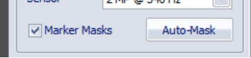
Fig. 184 Auto-Mask
Manual Masking
Click on the Marker Mask Tool at left-hand side of the menu.
Then use the mouse to draw rectangles on each camera representing the region to be masked. See Fig. 185.
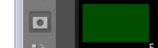
Fig. 185 Manual Masking
Define global coordinate system
Take the box with the Calibration kit that has a T-shape wand showing serial number 1815 and length 601.5mm.
For now, we only need the L-shape: it needs to be mounted on a large L-bracket made of aluminium profiles as in the image below. See Fig. 186.
Place the L-bracket with the L-shape inside the RoI in the middle of the water tank, where you want the global coordinate system to be.
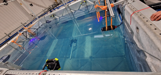
Fig. 186 Calibration Kit
The intention here is to have the L-shape visible by all cameras. See Fig. 187.
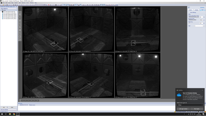
Fig. 187 Calibration Kit Visible
Next, take the T-shape wand 601.5 mm. See Fig. 188.
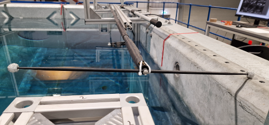
Fig. 188 Calibration Kit T-Shape
Make sure to indicate the details of this kit (consisting of the T-shape wand and L-frame) by going to Project Options -> Camera System -> Calibration. See Fig. 189.
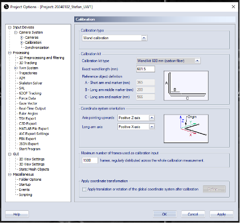
Fig. 189 Calibration Kit Details
Click the wand icon on the top horizontal menu. See Fig. 190.

Fig. 190 Calibration Kit Wand
and, on the window that pops up on the screen, choose the calibration time (e.g. 60 seconds) and
the Delay in calibration (e.g. 5 seconds), then hit OK. See Fig. 191.
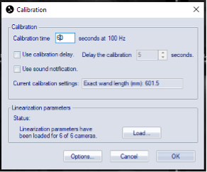
Fig. 191 Calibration Kit Wand Window
Take the T-shape 601.5 mm wand and start waiving it in the RoI. Combine the two motions below to create a waiving motion:
Move the wand round the tank in a spiral motion with the head of the
T-wand vertical.Move the wand up-down with the head of the
T-wand horizontal.
Try to cover as much as possible of entire RoI (not just a small region). Once the data has been recorded, you can view and play it again.
Creat a Rigid Body
First of all we need a non-symmetric patter made with markers. See Fig. 192.
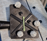
Fig. 192 Rigid Body
Make sure the following three windows are available on the screen. hit View -> Trajectory Info -> Unidentified, then hit Labeled and finally hit Discarded. See Fig. 193.
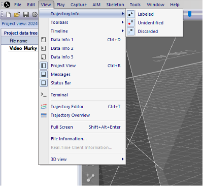
Fig. 193 Rigid Body Windows
Click th Record button. See Fig. 194.
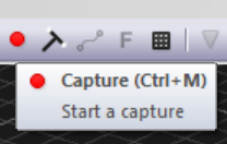
Fig. 194 Rigid Body Record
Start capturing a short video that contains the pattern. See Fig. 195.
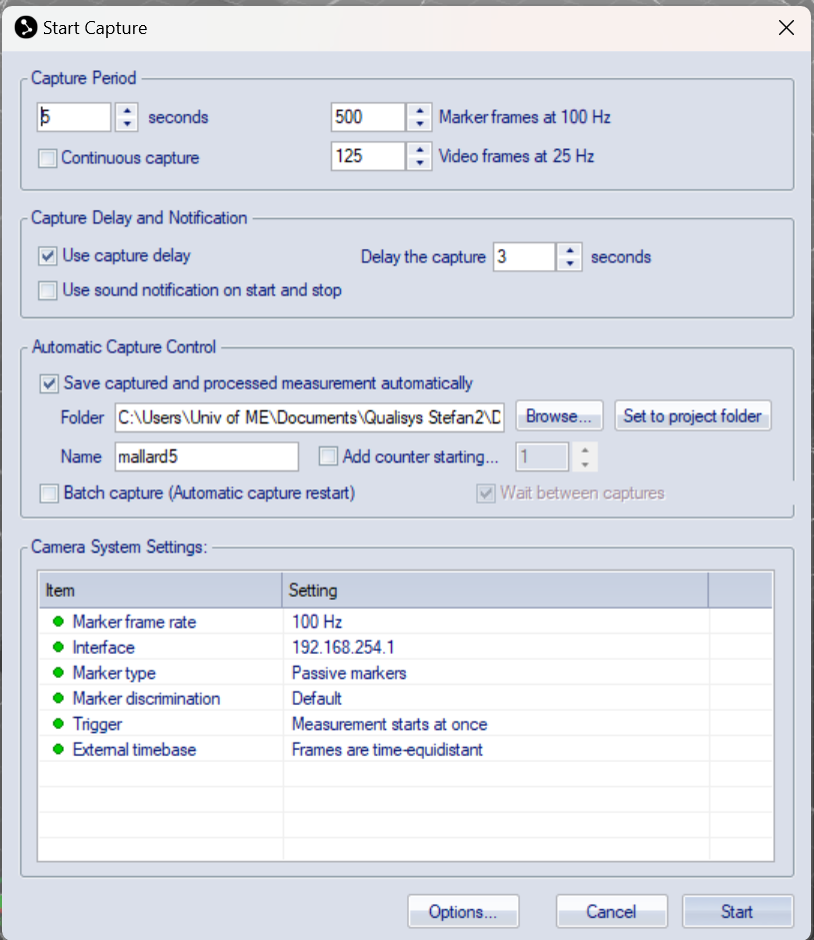
Fig. 195 Rigid Body Capture
Replay the recording and pause somewhere (hit spacebar).
Markers’ data will show up in the box Unidentified trajectories.
Click on each marker that forms the pattern, then drag and drop them into the Labeled trajectories.
Give individual markers and associated trajectories names, e.g. marker1, marker2, etc.
Select all markers that form a pattern using Shift + select, or Ctrl + click on each marker ball.
Now, right-click with the mouse -> Define rigid body (6DOF) -> Average of frames. See Fig. 196.
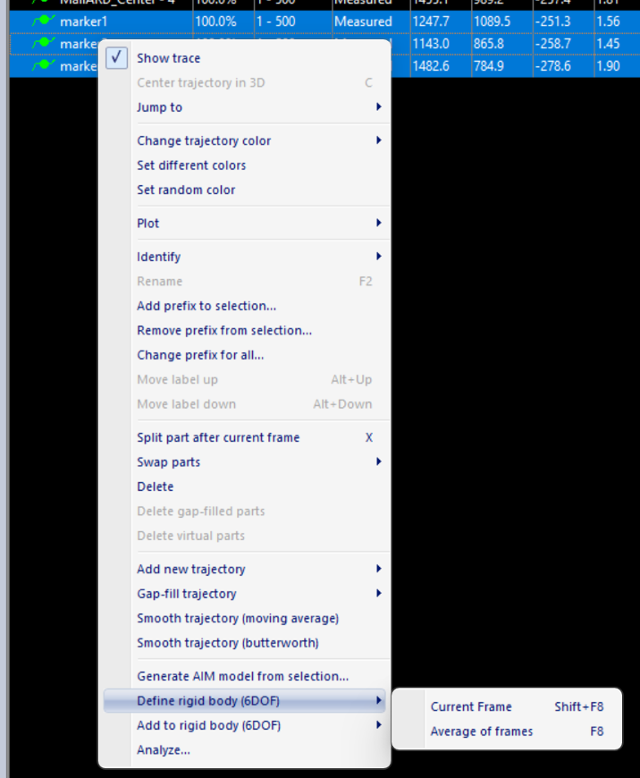
Fig. 196 Rigid Body Define
Then, give it a name, e.g. Rigid Body 1. See Fig. 197.
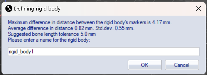
Fig. 197 Rigid Body Name
Note
Make sure the name does NOT have any spaces, and does not start with a number, otherwise it would fail to work on ROS.
Next, we need to adjust the body coordinate system, i.e. the xyz-coordinate axes. For that, click on the settings button from the horizontal top menu. See Fig. 198.

Fig. 198 Rigid Body Settings
And go to Processing -> 6DOF Tracking. See Fig. 199.
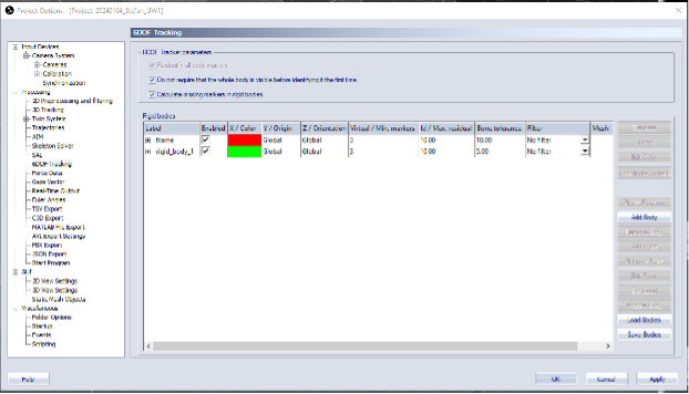
Fig. 199 Rigid Body 6DOF
Then, click on Translate button and adjust accordingly. See Fig. 200.
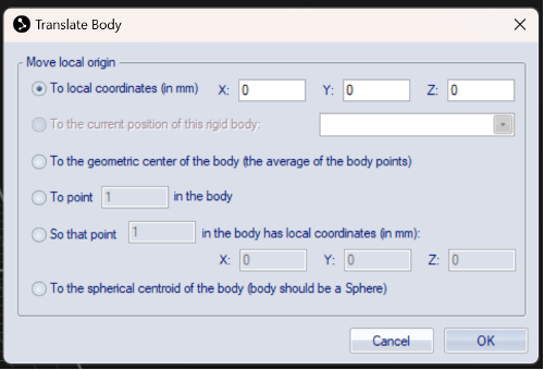
Fig. 200 Rigid Body Translate
You can also click on Rotate. For example, below we set up the y-axis going through points 1 and 3. See Fig. 201.
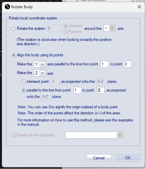
Fig. 201 Rigid Body Rotate
To know which point has what number, click on a point and look at the number shown in the upper right corner of the white window. For example, below the point 2 was clicked on. See Fig. 202.
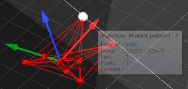
Fig. 202 Rigid Body Point
To check the list of all rigid bodies stored in QTM, go to Project Options -> Processing -> 6DOF Tracking. See Fig. 203.
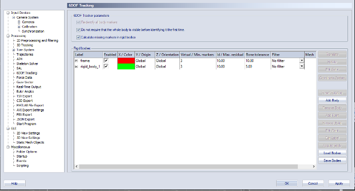
Fig. 203 Rigid Body List
For instance, below is shown the frame rigid body. See Fig. 204.
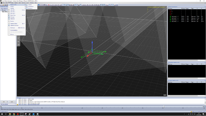
Fig. 204 Rigid Body Frame
Close the active window inside QTM with clicking the second X from top to down, on the upper right corner of the screenshot above
and when the dialog box appears, select Yes, save settings.
Click the New icon to start streaming (broadcasting) data of the rigid bodies defined above,
across the network (the Netgear switch). See Fig. 205.
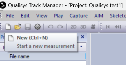
Fig. 205 Rigid Body Stream