Vicon Applications
Object Tracking
Before do tracking, you need to calibrate the Vicon Vero 2.2 system. The calibration process is described in the Calibration page.
To do tracking,
first of all you need to creat a Create a non-symmetrical pattern using vicon markers, that will eventually be attached to the robot that we intend to track. See the Fig. 115 as an example.
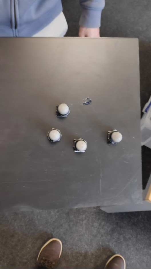
Fig. 115 Vicon non-symmetrical pattern
In the software, Vicon tracker -> Objects -> select using Alt + click (or Ctrl + click) to crop using mouse the ensemble of markers. See the Fig. 116.
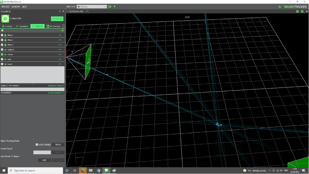
Fig. 116 Vicon crop
Give it a name by filling in the white box next to
Create object, and hit Create button. Say we give this object the name stefan_1 as an example in the Fig. 117.
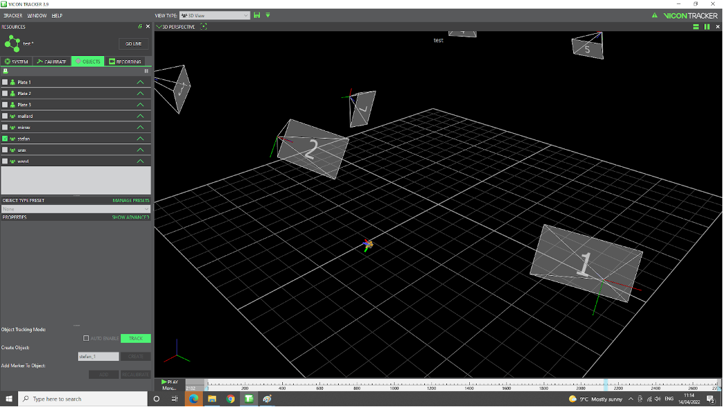
Fig. 117 Vicon create object
By selecting the
objectalone that we are interested in, thenclk Track button, only that specific object will be visible on the scene.
Recording Locally
To record the tracking data locally, you can use the Vicon Tracker software. The steps are as follows:
Select Recording -> Trial name give it a name, e.g. test1001, then
click Start, move the object (run intended the experiment), thenclick Stop. See the Fig. 118.
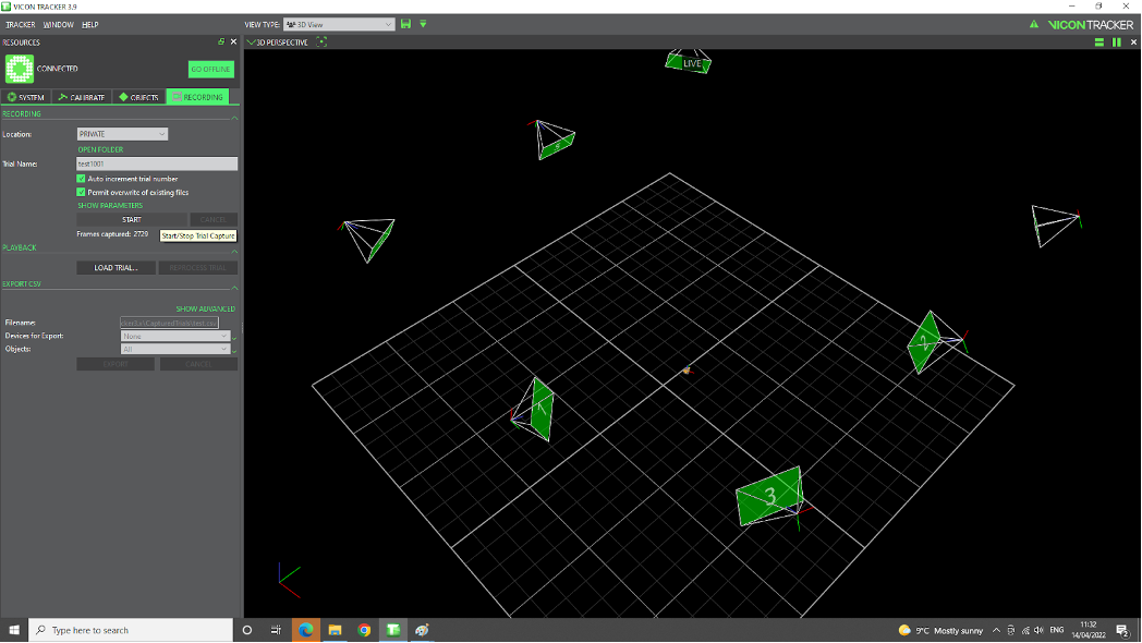
Fig. 118 Vicon recording
click on
Open Folderbutton to locate the files saved (e.g. test1001.system, test1001.x2d, test1001.xcp), as shown in the Fig. 119.
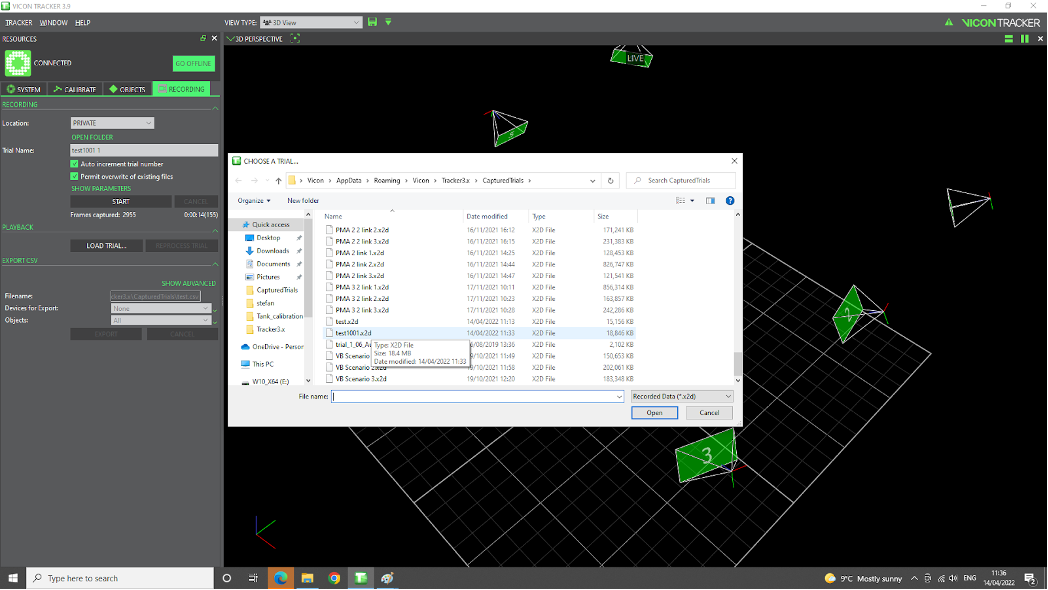
Fig. 119 Vicon recording folder
Playback
To playback the recorded data, you can use the Vicon Tracker software. The steps are as follows:
Recording -> Playback -> Load trial. indicate a file name (e.g. trial1001.system). Immediately we see
Go Offlinechanges toGo Live.Click the Playbutton located on the lower part of the screen. See the Fig. 120.
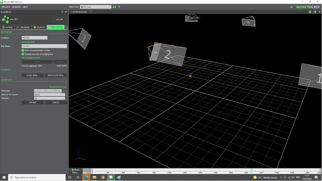
Fig. 120 Vicon playback
Note
To go back (and exit Playback mode), clk on Go Live again making it change to Go Offline.
ROS Bridge
THe ROS repo presented in Vicon Vero 2.2 page. However, you can use vicon_bridge to bridge the Vicon data to ROS. The steps are as follows:
$ cd ~/vicon_ws/src
$ git clone https://github.com/ethz-asl/vicon_bridge.git
$ cd ~/vicon_ws
$ catkin_make
$ source devel/setup.bash
$ rospack profile
Now in the terminal, you can run the following command to set the Vicon IP:
$ nm-connection-editor
Then, click on Ethernet -> click Add -> select Ethernet, then set config as shown in the Fig. 121.
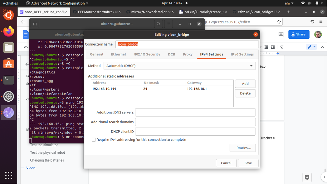
Fig. 121 Vicon ethernet config
Note
If the connection is not stable you can change the method into Manual.
Now, Plug one cable into [laptop] and another one in the PoE switch, next to any of the cables going to the Vicon cameras. Then test the Network connection by running the following command:
$ ping 192.168.10.1
To check the IP details, run the following command:
$ vi ~/vicon_ws1/src/vicon_bridge/launch/vicon.launch
and make sure this line appears:
<arg name="datastream_hostport" default="192.168.10.1:801"/>
Now, you can run the following command to start the Vicon bridge:
$ roslaunch vicon_bridge vicon.launch
To check the data, run the following command:
$ rostopic list
$ rostopic echo /vicon/stefan/stefan
Note
stefan is the name of the object as selected on vicon-PC, Vicon Tracker -> Objects. You can change it to the name of the object you are interested in. See the Fig. 122.
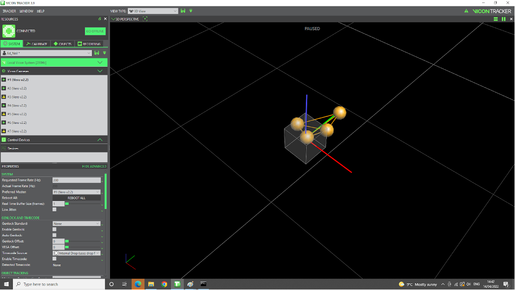
Fig. 122 Vicon object name